Transport Analysis Specification
1.0 General
The transport analysis can be used to determine if a vessel is suitable to transport a given cargo. The analysis includes general floatation condition, stability and motion response behavior. To run the analysis the user should define the vessel, the cargo, and the environment and should select the type of analysis required. Based on this data the analysis will run on our server and the results will be sent back to the user right after the analysis is finished.
In order to limit the input data several assumptions and simplifications have been made. This will mean that your transport analysis will never be fully representative with reality, but the assumptions and simplifications made are a good first estimate which will give results accurate enough for a first assessment of the transport.
WARNING: Do not use the results of this analysis for final design or real transports without thoroughly checking of the input and results by an experienced Naval Architect.
The following three analysis types are available:
1) Static Stability
This analysis will calculate the general floating condition of the vessel and will report static stability properties of the floating vessel.
2) Full Stability Analysis
The report of this analysis will include the full stability curve and an intact and damaged stability check according Noble Denton.
3) Full Stability and Motion Analysis
Output will include the full stability report and the motions of the vessel for the specified seastate.
2.0 Definition of Model
The transport model consist of 3D geometrical vessel model either predefined or defined with user entered main dimensions. Together with a definition of the cargo and the environment, the transport analysis is performed and reported back to the user.
The following table presents the user input data for the transport analysis:
| Name | Variable | Comments | ||||||||||||||||||||||||
| Barge Type | Type | Select a barge form the list Your own vessel can be in the list. Contact Marine Online to learn the details. |
||||||||||||||||||||||||
| Length, Width, Height | L, B, D | Enter barge dimensions if not pre-defined | ||||||||||||||||||||||||
| Draft | T | The draft will be calculated using the weight of the barge and the cargo and water ballast. The barge will be ballasted to a small trim aft down of 0.2 degree. If Optimum draft is selected the barge will be ballasted down to 50% of the barge height. This draft will in general give the best stability values. | ||||||||||||||||||||||||
| Cargo Weight | Cw | The mass of the cargo defined in metric tonnes | ||||||||||||||||||||||||
| Cargo VCG | Cv | The vertical center of gravity of the cargo defined in meters above barge main deck | ||||||||||||||||||||||||
| Wind | W | Wind speed at 10 m above sealevel in knots. This wind speed will be used to calculate the wind overturning moment assuming an ABS wind profile. | ||||||||||||||||||||||||
| Wave Height | Hs | To define a seastate for a motion analysis you need to give the significant wave height. Significant wave height is defined as follows: The average of the 1/3 highest waves in a a three hour seastate. This value corresponds best to the observed waveheights at sea by an experienced sailor. Hs is defined as the height from wave crest to trog. For a valid transport analysis acoording to Noble Denton Rules, the Wave height and wind strength should be based on the 10 year return monthly condition for the location and the month of the transport. The following table presents a suggestion for these waveheights and winds based on location and season.
|
||||||||||||||||||||||||
With the standard analysis mode the following data can not be controlled by the user and is automatically generated for each run.
| Name | Variable | Comments |
| Barge Lightship weight | W | Defined as 0.13 * L * B * H This equation assumes that the vessel weight is 13 % of the total vessel volume. |
| Barge CoG | BCOG | The barge center of gravity has been assumed at midship and at 50% of the barge height |
| Barge inertia | BI | The barge mass inertia is taken as: kroll = B / 3
|
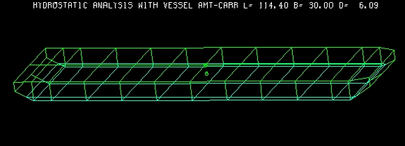
| Barge shape | The pre-defined vessels are true 3D models. The general cargo barge with user defined dimensions is shaped as follows:
|
|
| Barge Wind area | BA | The part of the barge above water will be taken as wind area. |
| Cargo COG position | CCOG | The cargo will be assumed amidships |
| Cargo inertia | CI | the cargo mass inertia is taken as: kroll = 10 (m) |
| Cargo Wind Area | CA | The wind area will be calculated using the weight of the cargo and the width of the vessel as follows: CA = Cw / 0.2 / B (m2) This equations assumes that the weight density of the object is 0.2 ton / m3 and that the width of the object is equal to the width of the vessel. The wind area will be assumed to act in CCOG |
| Seastate Period range | Minimum Peak Period = (13 * Hs)^0.5 Maximum Peak Period = (30 * Hs)^0.5 |
|
| Seastate Spectrum | Jonswap with peakness shape factor 3.3 | |
| Seastate Spreading | cos^2 Spreading assumed | |
| Seastate Headings | The following wave headings are used: 0 : Head Seas |
|
| Maximum Response | The maximum responses are calculated assuming a Rayleigh distribution of the extremes. Rayleigh factor = 1.86 The most probable maximum assuming a three hour exposure is calculated as follows: Max. Response = 1.86 * Significant response |
|
| Stability Rule Check | Guideline used: Noble Denton Static Stability requirements:
|
|
3.0 Analysis Method
The vessel model is represented by a 3-D plate representation of the hull outer surface. Most models also include the inner ballast compartments as 3-D Plates.
3.1 Static Analysis
The static analysis will define a ballasted condition based on a pre-defined floating condition using the vessel hull model and the mass properties. To reduce motion response of the vessel, wing tanks will be flooded first if possible. After this analysis the found equilibrium condition will be reported together with various static properties of the floating condition.
If a full stability analysis is selected, the stability range of the vessel will also be calculated and a rule check of the results will be done. This stability range is determined by setting the vessel at a range of fixed roll angles. For each roll angle, the program will iterate an equilibrium position for the other degrees of freedom and then compute the righting and wind heeling arms. This analysis will be repeated with one pre-defined compartment flooded to simulate a one compartment damaged condition. Finally both intact and damaged stability results are checked against a set of pre-defined criteria based on some selected rules.
3.2 Dynamic Analysis
If motion analysis is selected, a frequency domain dynamic analysis will be performed using the vessel hull at the intact floating condition. The result of the analysis will be the motions and accelerations of the cargo center of Gravity (CoG). These results can be used to estimate the seafastening requirements for the cargo.
The analysis is done as follows:
For head and beam seas the analysis results are tabulated in a summary table and compared to the standard accelerations as advised by Noble Denton.
| Analysis Results | Noble Denton | ||||
| Motions | Acceleration | Motions | Acceleration | ||
| Head seas | Pitch | 12.5 deg | 12.5*(2 pi/10)^2 | ||
| Surge | g*sin(12.5) | ||||
| Heave | 0.2 * g | ||||
| Beam Seas | Roll | 20 deg | 20*(2 pi/10)^2 | ||
| Sway | g*sin(20) | ||||
| Heave | 0.2*g | ||||
Based on these results the user can decide which approach can be used to design the seafastening.
NOTE: The results of this analysis may not be used for final design as the results are based on a model using several simplifications.